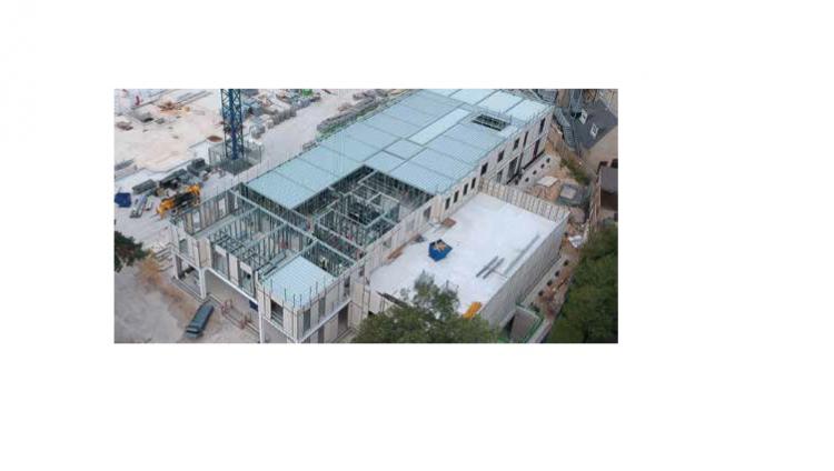
Fire Resistance of Light Steel Framing

Fire Resistance of Light Steel Framing
Mark Lawson and Andrew Way of the Steel Construction Institute (SCI) discuss issues related to fire resistance of buildings and introduce upcoming new SCI guidance on the fire resistance of light steel framing.

Since the Grenfell fire disaster, the question of the fire safety of medium and high-rise residential buildings has been heightened. Clients and checking authorities are understandably concerned about fire safety, particularly for buildings that exceed 18m in height, and Regulations have been introduced to prevent the use of combustible materials in external walls. SCI has been working with members of the Light Steel Forum and other industry experts to update
design guidance on the fire resistance of light steel framing which is well established as a construction system for medium-rise residential and mixed use buildings.

Steel has well-known properties at elevated temperatures and comprehensive design data is presented in BS EN 1993-1-2 and formerly in BS 5950-8 (dating from 1990). BS 5950-8 was the first fire engineering code worldwide and it influenced Eurocode developments. The critical temperature of structural steel beams and columns is taken as 550°C for the design of the fire protection to these members and this critical temperature increases as the proportionate loading (known as the load ratio) on the member reduces. Structural engineers are familiar with the design approach for structural steel but the application of methods for cold formed steel is the subject of the recent work by SCI.

Light steel framing has gained a market share because one of its benefits is that it is non-combustible and does not add to the fire load of the building, which are in addition to its other benefits. It may be used with joisted floors or increasingly, with composite floor slabs that are supported by the light steel loadbearing walls.

Strength Retention of Cold Formed Steel
Cold formed steel has slightly reduced strength retention properties at elevated temperatures compared to structural steel H sections and hollow sections because of the influence of local buckling of its thin profile. Nevertheless, the strength reduction factor (SRF) for Class 4 sections at 500°C is still 0.53 of the nominal yield strength. This means that a light steel section can support the reduced loads at the fire limit state up to this slightly lower critical temperature.

Light steel framing differs from structural steel in that it is a planar construction system. The 2D walls and floors are protected by layers of Type F or similar fire rated plasterboards. In the last three years, an unprecedented number of loaded fire tests have been performed by light steel framing and plasterboard suppliers to satisfy 60, 90 and 120-minutes fire resistance requirements for loaded walls and floors. 

A fire test on a loaded wall is generally performed using the thinnest steel section in a range with the highest sensible load that can be applied by the test house. Temperatures are measured on the flanges and web on the C sections at a number of positions, so that the critical temperatures can be related directly to the load that is applied for the particular wall build-up. This is the so called ‘load ratio’ method.

With this test information, the design of a C section with thicker steel or with another wall height from that tested can be calculated using the method developed by SCI. The only issue that affects the design solution is then the effect of non-uniform heating through the C section for fire on one side, which has two opposing effects: it causes some thermal bowing which adds to bending effects (or P-effects); but on the beneficial side, the centre of resistance of the C section moves towards the cooler unexposed flange. Generally the two effects can cancel each other for the normal range of wall lengths but the loss in buckling resistance due to thermal bowing is taken into account.

Design Methodology for Loaded Walls 
The formula that links the design resistance of a loaded C section in a planar wall at the fire limit state to its buckling resistance in normal conditions is given by:
Nb,Rd,fi =k1 Nb,Rd SRF(θref)

Nb,Rd,fi is the axial load that may be supported in fire.

Nb,Rd is the buckling resistance of the C section in normal conditions taking account of the effective length for buckling.

SRF(θref) is the strength reduction factor for Class 4 cold formed steel section.

(θref) is the reference steel temperature for a non-uniformly heated section that takes account of non-uniform heating.

k1 is a coefficient that takes account of thermal bowing effects and is typically 0.8 for walls supporting joisted floors or 0.9 for walls supporting composite (concrete) floors due to the greater restraint provided by the stiffer floor.

The procedure uses measured temperatures in a test and so it is important that this data is obtained as temperature versus time in order to be able to back analyse the test. It is a pre-requisite that a valid test result is obtained for the particular wall buildup for use of the calculation method. The complete design guidance will be presented in a new SCI publication P424, and its accompanying Annexes giving the full design methodologies for light steel loaded walls and floors. 

External Fires on Loaded Walls
The same approach may be applied to external walls but here the question is what is the fire severity of an external fire? At present, there is no agreement on this as logically it should be less severe than a fully developed fire within a compartment in a building. The approaches that have been proposed for an external fire are: 

  • A fully developed ISO fire curve, but with a cut-off temperature of 680°C as permitted by BS EN 1363-2 for external walls. With this, the fire endurance will be increased relative to an equivalent internal wall, but this tests is rarely performed.

  • A fully developed ISO fire curve, but with compliance for an external wall taken as a notional fire resistance of 60 minutes or as a maximum of 30 minutes less than for the internal structure. This is a simple way of recognising that a natural fire occurring outside a building or emanating from windows and radiating back onto the external wall has a lower effect than a fully developed fire internally assuming adequate fire stopping around windows etc.

  • A fully developed ISO fire curve without any reduction

    The external sheathing boards that are used are very robust structurally but do not necessarily possess the inherent insulation characteristics of gypsum-based plasterboard. Furthermore, for buildings more than 18m high (currently for England), noncombustible insulation and sheathing boards are required.

    Composite Floor Slabs
    Composite floor slabs can provide up to 120 minutes fire resistance without requiring a fire protected ceiling by virtue of the embedded reinforcing bars in the deck ribs. Guidance on the fire resistance of composite slabs is given in BS EN 1994-1-2 and in the former BS 5950-8, and SCI publication P375 - Fire Resistance Design of Steel Framed Buildings.

    Design Methodology for Loaded Floors
    Loaded floors differ from loaded walls in that the effects of thermal bowing do not add to the applied moments and the critical temperature is taken as the bottom flange temperature. Also, for floors, the plasterboard ceilings can become detached as they weaken in fire. The design approach for loaded floors is based on a similar approach to walls but a constant coefficient of 0.6 is used and the buckling resistance can take account of the restraint offered by the floor boarding, as follows:

    Nc,Rd,fi =0.6 Nb,Rd SRF(θexposed)

    However, most joisted floors are designed for serviceability limits of deflection and so their load ratio will be less than 0.3, so that their critical  temperature will be similar to that of loaded walls.

    For more information visit:
    www.steel-sci.com
    www.lightsteelforum.co.uk
  •  

    Stay in touch:

    Industry partners
    Twitter 1 Jan