Cladding: Expertise and engineering
Andrew Way, Associate Director at the Steel Construction Institute (
SCI), discusses issues surrounding light steel framing with continuous masonry cladding.
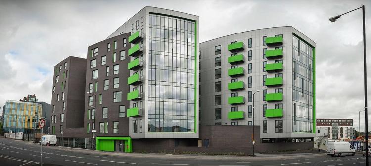
Masonry cladding is commonly used on load-bearing light steel framed buildings. The masonry cladding is generally supported from the ground or a podium structure and the light steel frame provides lateral support to the cladding. Depending on the height of the masonry cladding, it may be designed to be vertically supported by the structural frame at specified intermediate floor levels. However, it is technically and economically beneficial to consider designing taller continuous heights of masonry cladding which are supported from the ground or a podium structure.
Uninterrupted ground supported masonry has been used successfully on light steel framed (LSF) buildings up to eight storeys (approximate height 22m). There are several factors to be considered in the design of continuous uninterrupted masonry cladding for LSF buildings, these factors are:
• Ability of masonry to support its self-weight over the uninterrupted height
• Effect of concentrated local loads due to large window openings
• Differential movement between the masonry cladding and the light steel structure
• Avoidance of disproportionate collapse of masonry cladding
• Design of wall ties for local wind loads, especially at corners
• Implications for the design of the structural frame.
Ability of the Cladding to Support Self-Weight
The masonry cladding must be designed to have sufficient strength to resist the applied vertical loads. Openings within the masonry cladding for doors and windows will cause loads to be concentrated in the masonry between openings, this effect should be considered in the design of the masonry.
Differential Movement
Guidance relating to differential movement between masonry cladding and the structural frame is provided in PD 6697 and BS 5628-1. LSF has an advantage in this regard because, as identified in PD 6697, steel frame structures are not subject to shrinkage movement and so vertical differential movement is due only to thermal and moisture movements of the cladding. These effects are accounted for by an allowance of 1 mm/m which is stated in PD 6697 and Chapter 6.10 of the NHBC Standards. Although BS 5628-1 has been superseded by PD 6697, it provides useful guidance which is not directly included in PD 6697. BS 5628-1 recommends that:
• Calculated differential movement is less than 30mm
• Separate lintels are used for outer and inner leaves
• Movement-tolerant wall ties should be used
• Soft joints under sills should be provided.
An important point to recognise is that BS 5628-1, Clause 25.3.2 'Limitation on uninterrupted height' is applicable to twin leaf masonry cavity walls and that the limitations in the clause should not be applied to steel framed buildings with masonry cladding.

Disproportionate Collapse Avoidance
Masonry cladding should be designed to avoid disproportionate collapse of several storeys of cladding by an accidental event (e.g. vehicular impact). It is recommended that a layer of bed joint reinforcement should be included in the masonry at each floor level. Masonry which is not directly part of the damaged area is tied to the frame through the wall ties and hence is prevented from falling from the structure. Significant vertical distortion of the masonry may occur, but this is deemed acceptable in an accidental load case.
Implications for Frame Design
One benefit of masonry supported by the ground or a podium is that the light steel frame does not need to be designed to carry the additional weight of the cladding. However, the weight of the masonry supported by the ground or a podium should be included in the permanent actions used for the specific calculation of the Equivalent Horizontal Forces for Eurocode design, or the Notional Horizontal Forces for design to BS 5950.
Design of Wall Ties
The wall ties must be designed to resist local positive and negative wind pressures, which depend on the building location, the building height, the site exposure and the location on the building façade.
The required length of wall tie will depend on the cavity width and its embedment length. The required fixing length depends on the thickness of external insulation and the sheathing board. For semi-rigid or flexible insulation, compression sleeves should be used around the fixings to provide the necessary support. Specification and installation of wall ties must be in accordance with the manufacturer's instructions.
Masonry cladding can be used on LSF buildings with an uninterrupted height of more than five storeys. There is no requirement in either BS 5628 or in BS EN 1996 for masonry cladding to be supported by the structural frame at specific intervals. However, the junction details and ties must make specific allowance for the predicted relative movement.
Further guidance with examples of LSF buildings which have continuous masonry cladding over five storeys is provided in SCI Technical Information Sheet P426. The guidance has been produced in association with the Brick Development Association and is freely available to download from The
SCI Information Portal.